Lincoln Infinity Series Annual Maintenance
When working on or around trap machines, always wear eye protection and proceed with extreme caution. Trap machines have pinch points and components that move rapidly. Safety information included in your owner’s manual must be read and understood before performing work on any trap machine. Prior to beginning this maintenance process, release the trap and disconnect the power to ensure it is safe to work around.
This is a general guide for all Lincoln Infinity Series Automatic traps, some images may not match your exact machine.
Table of Contents:
Clear Target Debris:
Before inspecting any individual parts of the trap, make sure it is free of target debris. Remove all debris from the areas inside of the magazine, as shown in Figures 1.1 and 1.2. Also, remove any target chips stuck in the target guide bar as shown in Figure 1.3 (The guide bar is not present on all models). Clearing debris can be done by hand, with a leaf blower, or with compressed air.

Figure 1.1: Interior of magazine is clear of debris

Figure 1.2: Area around escapement roller is clear of debris

Figure 1.3: Target Guide Bar is free of target chips
Grease Points:
Recommended Grease: Mobilgrease™ XHP 222
Use the grease fitting, visible in Figure 2.1, to grease the magazine hub. One or two pumps from a grease gun are usually plenty. When the hub is fully greased, grease will start to push out around the tensioning nut or the base of the hub.
If your trap is mounted to a cart with serviceable wheels, add grease to wheel bearings by adding a few pumps of grease into the grease fitting in each wheel.
If servicing a Wobble or Oscillating trap, click here for additional grease points.

Figure 2.1: Magazine Grease Point
Lubrication Points:
We recommend Gibbs Brand Lubricant for most lubrication points, but other high quality lubricants are also suitable. Use a penetrating oil that is a corrosion inhibitor and a water repellent.
We also recommend Qmaxx Industrial Strength Extreme Penetrating Rust Solvent. This product is good for treating rust, and is also safe to use on plastics.
When applying lubricant, avoid overspray and clean off any excess lubricant. Excess lubricant can cause additional target debris to stick to the trap.
Apply lubricant to the flangette and collar bearings as shown in Figures 3.1a and 3.1b. On Rabbit and AR90mm traps, spray both sides of these components.

Figure 3.1a: Standard Clutch Assembly Lubrication Points
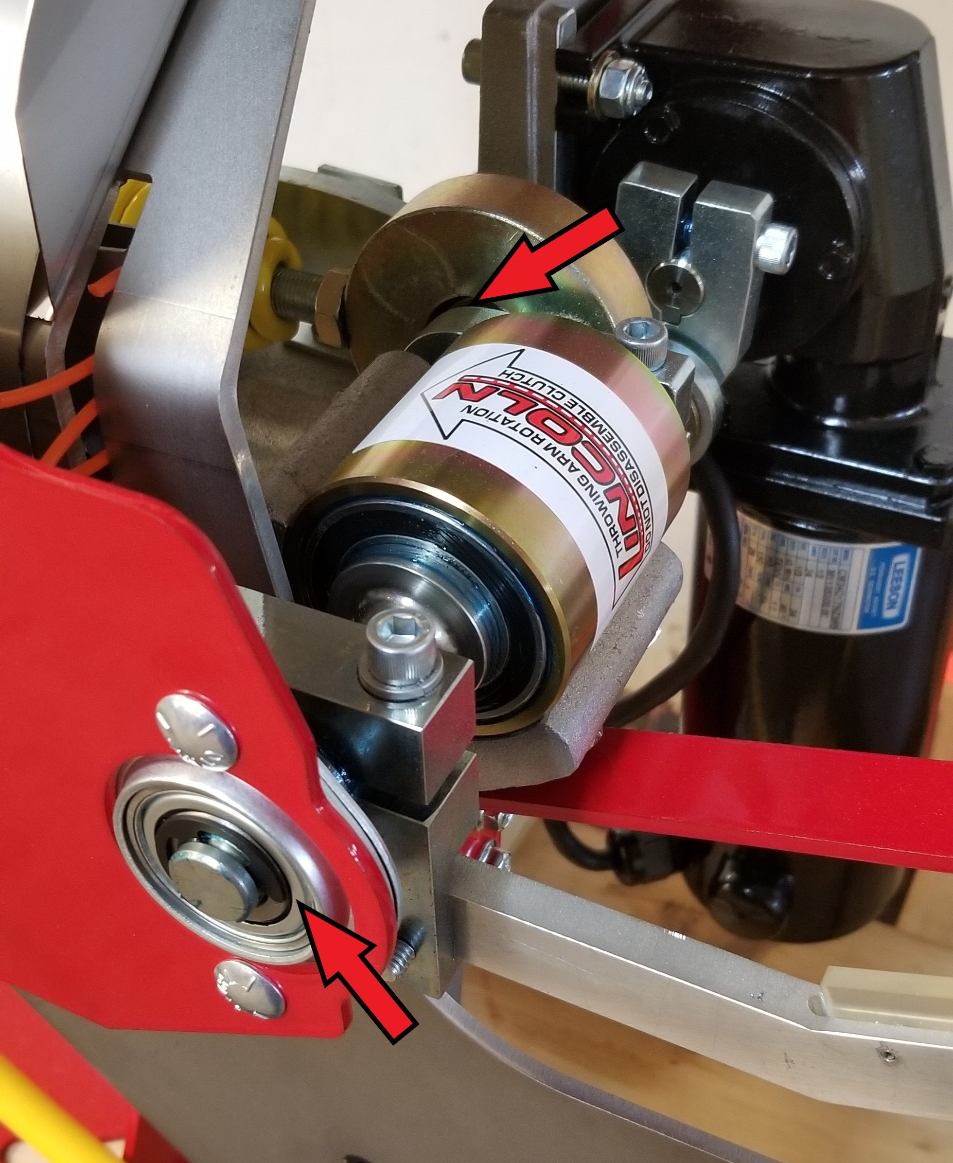
Figure 3.1b: Rabbit Clutch Assembly Lubrication Points
Apply lubricant to the bearing in the front of the main link, and at the base of the gearbox output shaft as shown in Figures 3.2a and 3.2b.

Figure 3.2a: Standard Main Link Lubrication Points

Figure 3.2b: Rabbit Main Link Lubrication Points
Apply lubricant to the bearing in the rear of the main link and into the bushing in the cast frame as shown in Figures 3.3a and 3.3b.

Figure 3.3a: Standard Lower Indexing Shaft Lubrication Points

Figure 3.3b: Rabbit Lower Indexing Shaft Lubrication Points
Apply lubricant to the upper mounting point of the indexing shaft as shown below in Figure 3.4a and 3.4b. To lubricate the bushing shown in Figure 3.4a, push up on the bottom of the shaft to create a gap between the bushing and the aluminum arm.

Figure 3.4a: Standard Upper Indexing Shaft Lubrication Points

Figure 3.4b: Rabbit Upper Indexing Shaft Lubrication Points
Apply lubricant to the bearings in each end of the indexing link as shown below in Figures 3.5a and 3.5b.

Figure 3.5a: Standard Indexing Link Lubrication Points

Figure 3.5b: Rabbit Indexing Link Lubrication Points
Apply lubrication to the indexing finger at the point shown in Figure 3.6.

Figure 3.6: Indexing Finger Lubrication Point
Apply lubricant to the escapement lever shaft and escapement roller shaft at the locations shown below in Figure 3.7. Do not get lubricant on the rubber O-ring, lubricant on the O-ring may result in improper target feeding.

Figure 3.7: Escapement Assembly Lubrication Points
Depress the rocker switch to the release position, a small gap will be visible between the switch and the housing as shown in Figure 3.8, apply plastic safe lubricant or contact cleaner into this gap, then rock the switch up and down a few times. This step is not applicable to Wobble or Oscillating trap machines.
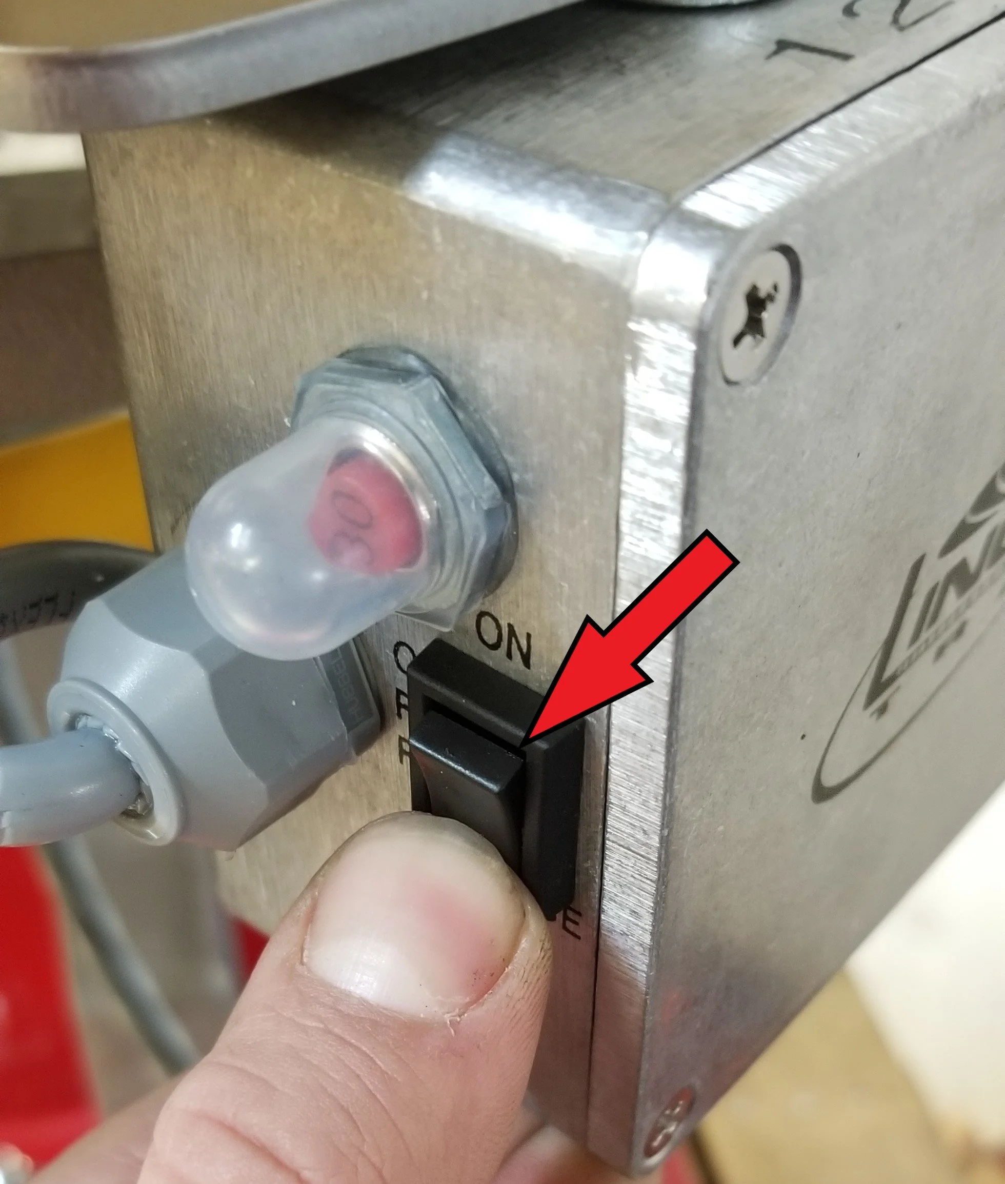
Figure 3.8: Rocker Switch Lubrication
Throwing Arm Inspection:
The throwing arm should be inspected for wear and damage. Click here for more information about inspecting the condition of your throwing arm.
Motor Brush Inspection:

Remove the vinyl caps from the brush holders, then remove the plastic brush cap and o-ring. Move the brushes in and out of the brush holder by hand, the brush should move smoothly along the length of the brush holder. If the brush is getting caught or does not move smoothly in the brush holder, there may be a burr in the holder that needs to be cleared.
Remove the brushes from the brush holder and wipe off any carbon build-up with a clean rag. Inspect the brushes for any signs of damage, if the springs are broken or deformed, or the wire shows any discoloration due to overheating, then the brushes must be replaced.

Figure 5.1a: Vinyl caps on brush holders

Figure 5.1b: Plastic cap and O-ring

Figure 5.1c: Motor brush

Figure 5.1d: Brush holder
Insert the inspected or new brushes into the brush holders and thread the plastic caps in place, making them finger tight. Seat the O-rings into the slot formed between the brush holder and the plastic cap. If the O-ring does not seat tightly into the slot, replace the O-rings. Inspect the vinyl brush holder caps, if they seem dried out or hard, they should be replaced. Apply plastic safe lubricant to the inside of the vinyl cap, then push the cap onto the brush holder, ensure that the O-ring stays seated in its slot. If servicing a Wobble or Oscillating Trap, repeat this process of inspecting and cleaning brushes for the angle and elevation motors.

Figure 5.2a: Brush Cap Slot
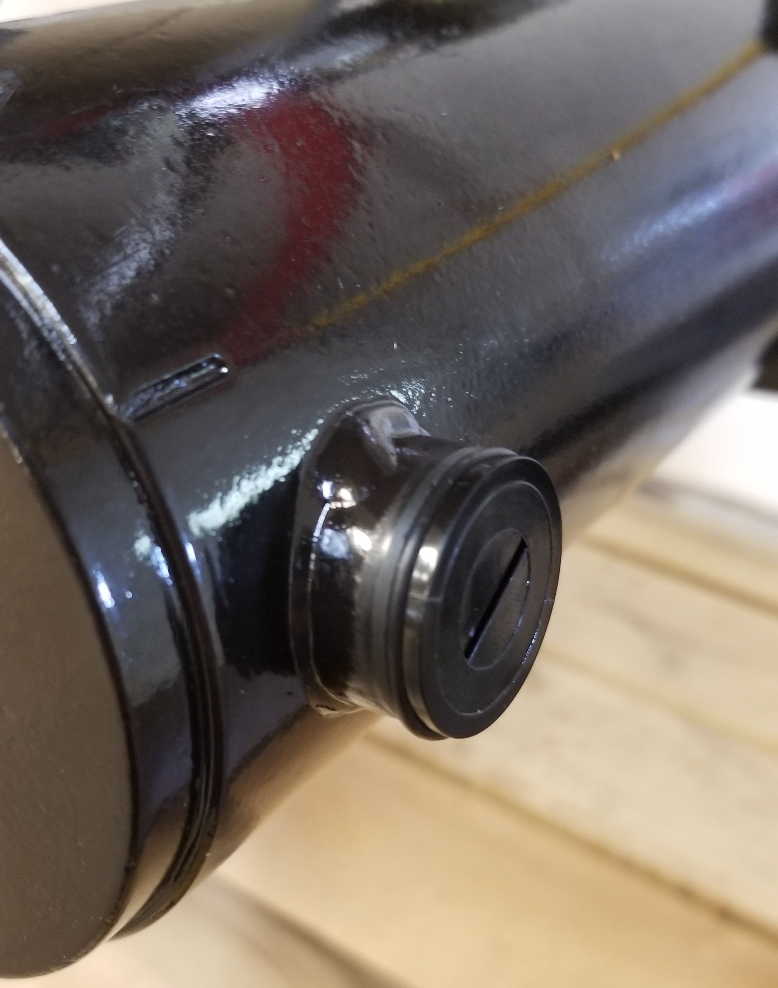
Figure 5.2b: Brush Cap with O-ring

Figure 5.2c: Lubricated Vinyl Cap
Magazine Inspection:
Inspect the magazine rails by firmly applying pressure on them in an attempt to rotate them, as shown in Figure 6.1. If any of the rails move, carefully tighten the square drive screws in the top of the rail. Over tightening these screws may result in stripping out the aluminum rail. If tightening the screws does not secure the rail, repair pins may need to be driven into the magazine from the bottom. Please contact our office at 717-274-8676 before attempting a repair on the magazine.
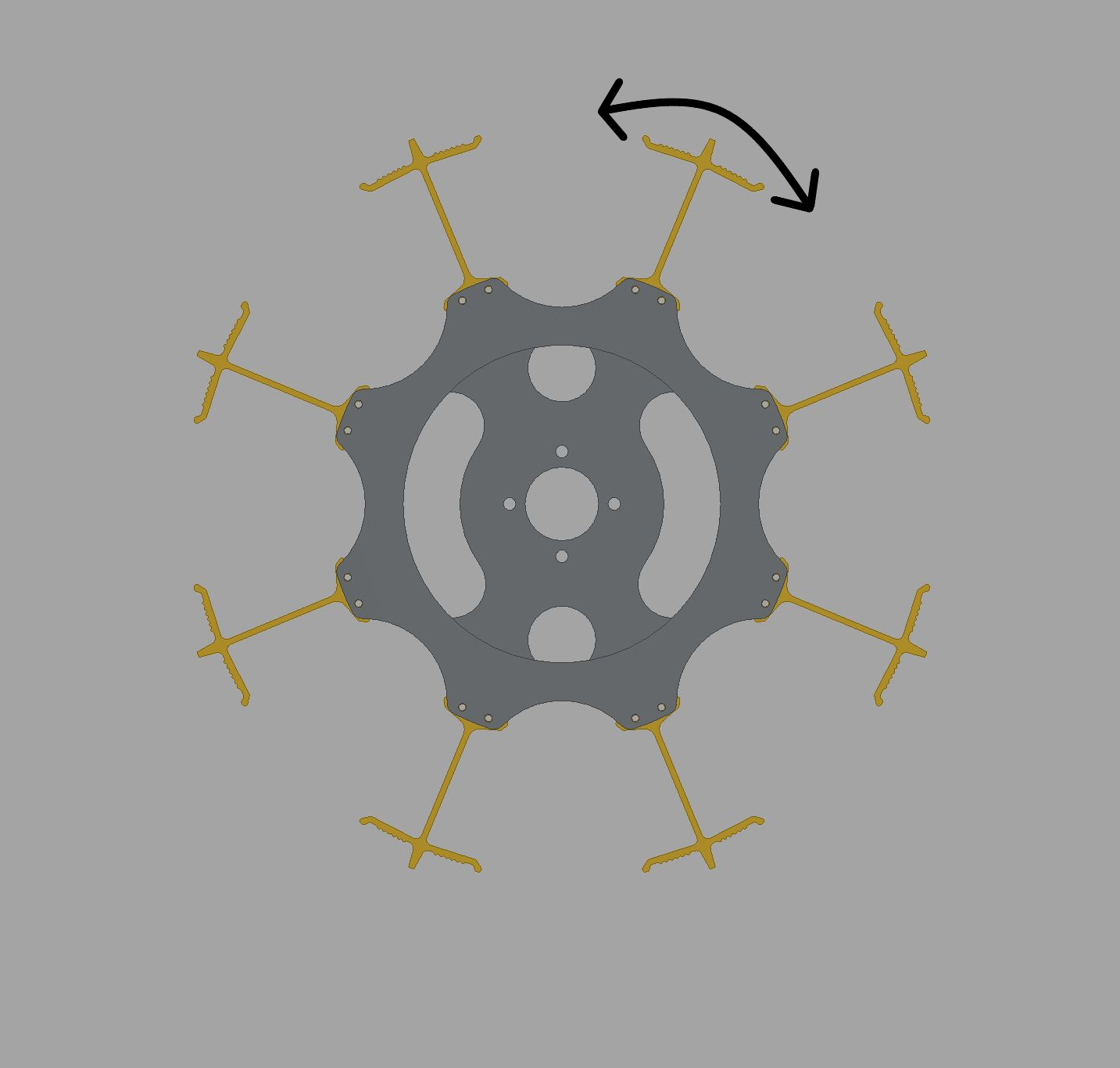
Figure 6.1: Magazine Rail Inspection
To check the tension of the magazine hub, empty the magazine and rotate it counterclockwise by hand. The magazine should have consistent resistance as it is turned. If the magazine rotates loosely, tighten the center nut, shown below using a 1-1/16” wrench or socket. Small adjustments can make a significant impact, tighten the nut in small increments, rotating the magazine after each adjustment to check the tension.

Figure 6.2: Magazine Tension Nut
Serviceable Parts Inspection:
All Lincoln Infinity Series traps have brushes and/or weedwhacker line that helps guide the target into the correct position. Brushes should be inspected for hardness and deformations. Some fraying of the brush bristles is okay, but brushes that no longer spring back into place must be replaced (AL150, AL351, AL550). The weedwhacker line should be replaced if worn down or broken-off pieces are found. It is best to replace all of the line at the same time.

Figure 7.1: Standard Brush

Figure 7.2: Rabbit Brushes and Weedwhacker Line
The positioning finger helps guide the target into place when feeding. Inspect the rubber tab for cracks. If the rubber is badly cracking, replace the positioning finger. Please note that the positioning finger is not present on Rabbit or AR90mm traps.

Figure 7.3: Positioning Finger
The indexing spacer allows the indexing block to move smoothly along the edge of the magazine plate. The spacer wears with use, the portion of the spacer that rides on the magazine plate will get thinner compared to the small portion of the spacer that does not make contact with the magazine plate. If this spacer is significantly worn, it should be replaced.
Figure 7.4: Indexing Spacer
The escapement O-ring pushes against the front stack of targets, suspending it while a single target it dropped onto the launch plate. This O-ring stretches and degrades over time. A worn O-ring can cause feeding issues resulting in broken targets. Inspect the O-ring for cracks and stretching. If the O-ring is not tight on the roller, or has cracks, it must be replaced. Some O-rings will have indentations from pushing against the inside of the magazine rails, these indentations are acceptable and do not require replacement of the O-ring.
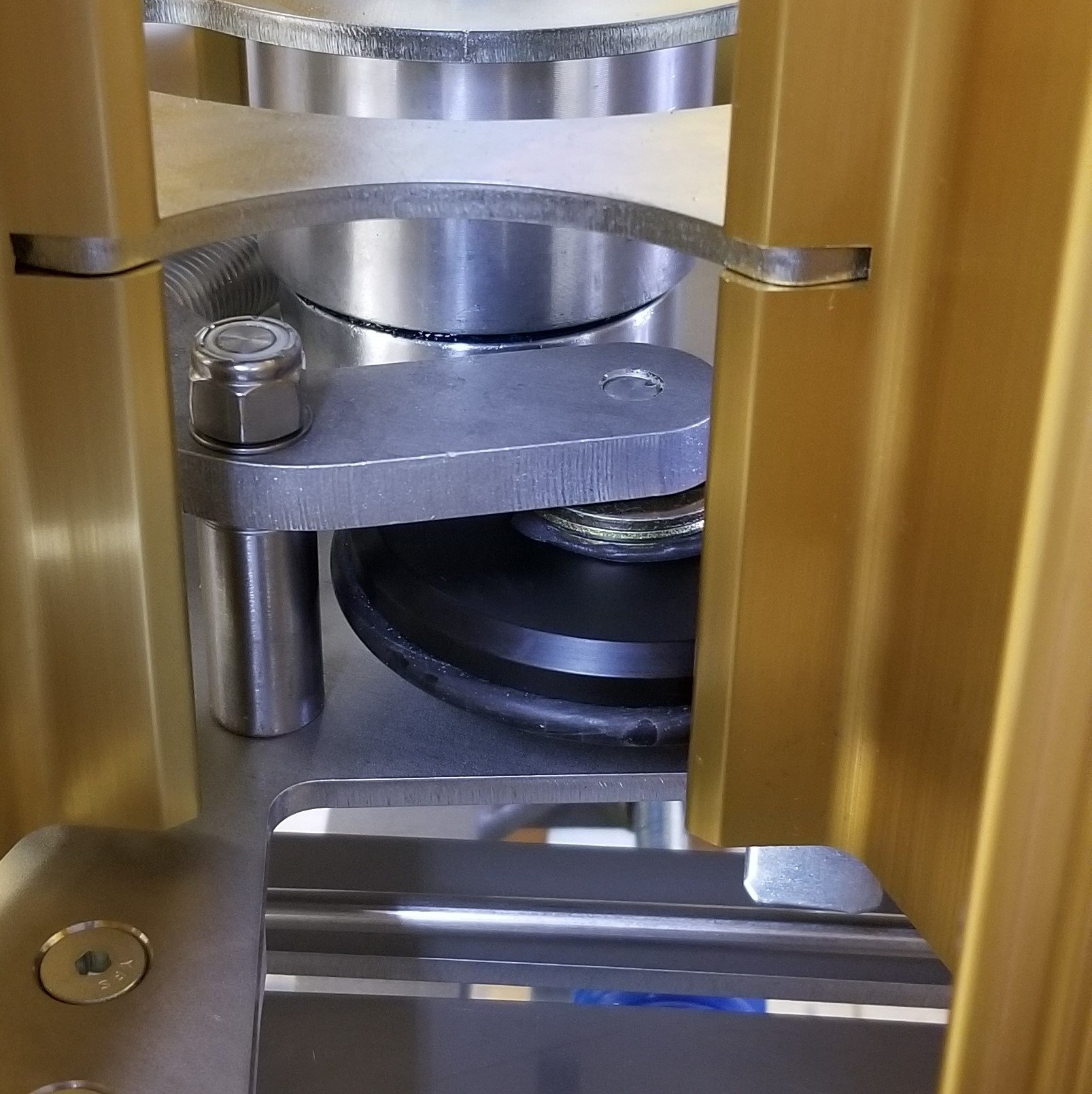
Figure 7.5 Escapement Roller O-Ring

Electrical System Inspection:
Check the release cord, ensure that the cable is fully clamped into the plug and there are no exposed wires as shown in Figure 8.1 below. The release cable should be secured by a strain relief attached to the back of the control box (or to the base of the machine if a Wobble or Oscillating Trap), make sure this strain relief is tight such that the cable can not slide through the strain relief.

Figure 8.1: Release Plug
Inspect the battery cables for damage that may be caused by rodents or shot. Slide the battery clip boots back off of the clips, clipping onto something will relieve the pressure on the boots and make them easier to move. Inspect the battery clip, if it is deformed or the spring is weak, it must be replaced. Verify that the wire hardware is tight and that all wire strands are under the hardware, there should be no loose wire strands.
Please Note: The battery clips must not be modified or spliced in any way. Modifying the length, termination point, or splicing in accessories can cause serious damage to the trap. Battery cable modifications void all warrenties on the trap. If you have any questions about connecting accessories, please contact our office at 717-274-8676.

Figure 8.2: Battery Clip
Inspect the cable that runs from the control box to the junction box, verify that there is no damage to this cable. Additionally, verify that cable going from the junction box to the motor does not show any signs of damage. If either of these cables show signs of damage, they must be replaced.
If servicing a skeet machine, the relay should be replaced during annual service. Instructions on how to replace the relay can be found here.
If servicing a Wobble or Oscillating Trap with a yellow handheld controller, inspect the cable for damage. Additionally, inspect the toggle switch boots on the yellow handheld for cuts, switch boots must be replaced if they are damaged.
Knife Adjustment:
Inspect that the target knife is in good condition, if the knife edge is damaged, it should be replaced. The knife-edge should appear straight as in Figure 9.1 below. Please be aware that the hardware securing the knife in these images may be different. To check the adjustment of the knife, put a short stack of targets in the magazine column prior to the one over the hole in the magazine plate. Rotate the magazine by hand, taking note of where the knife meets the target stack. The knife should slide in between the bottom two targets as shown in Figure 24. If the knife is bent or incorrectly adjusted, it will dig into one of the targets which can break them. If the knife is digging into the edge of the target, it must be adjusted up or down as needed.

Figure 9.1: Knife

Figure 9.2: Knife Adjustment
Additional Lubrication for Wobble and Oscillating Traps:
Wobble and Oscillating Trap machines have two additional grease points, add one to two pumps of grease into each of the fittings shown below.

Figure 10.1: Wobble Grease Points
Lubricate the bearings at both ends of the oscillating motor turnbuckle.

Figure 10.2: Oscillation Turnbuckle Lubrication Points
Lubricate the bearings at both ends of the elevation motor turnbuckle. This step is only applicable for the Wobble trap
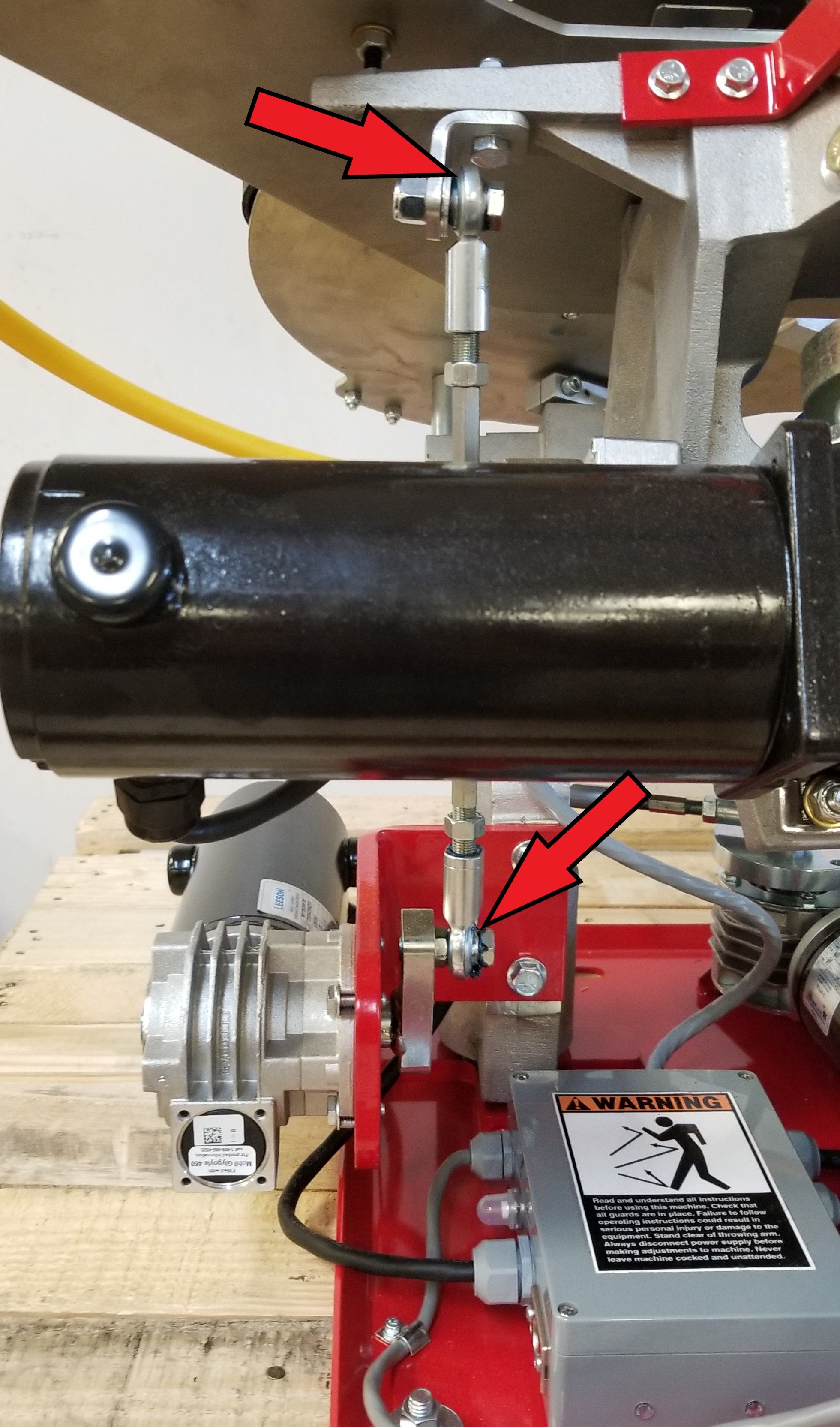
Figure 10.3: Elevation Turnbuckle Lubrication Points
Additional Lubrication for Skeet Machines:
Lubricate the bearings at both ends of the elevation turnbuckle, also lubricate the threaded adjustment rods.

Figure 11.1: Skeet Elevation Turnbuckle Lubrication Points
Lubricate the bearings at each end of the skeet windage turnbuckle, also lubricate the threaded adjustment rod.
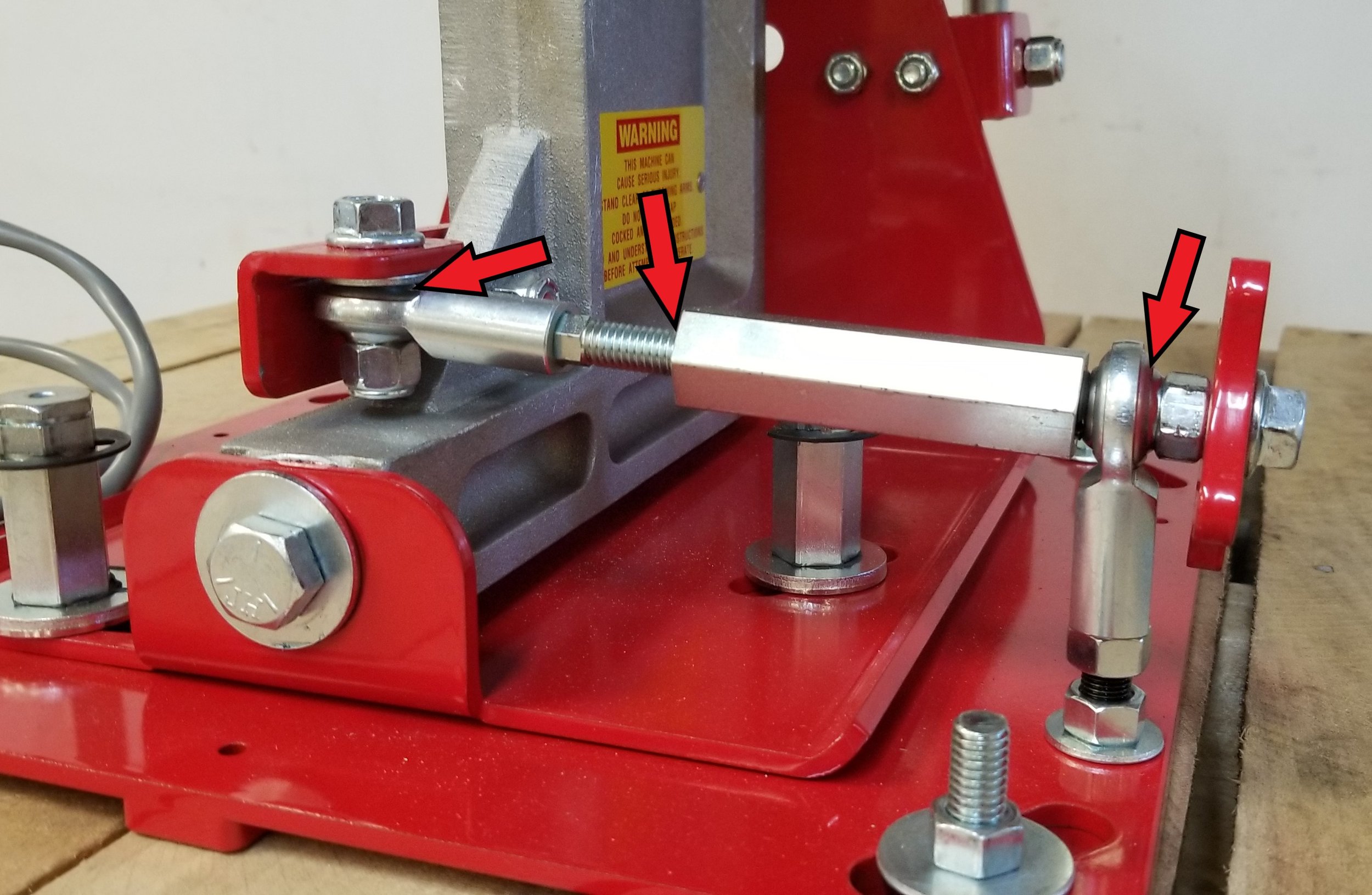
Figure 11.2: Skeet Windage Turnbuckle Lubrication Points